CAPACITORS
Why did the blue spark arc over?
...because the capacitor had to discharge...

Capacitors act as short circuits and discharge very quickly, this is why you see a bright blue spark in a circuit that involves a capacitors. They were designed by a mechanical engineer, maybe why it sparks in a most unsafe manner, not at all what an electrical engineer would have done. The spark can be both dangerous and cause damage to plugs... but they have been used for so long that who carers.
Capacitors discharge when the voltage source is removed. It may be noted that some devices, such as chargers, do not immediately turn off as the capacitor within its circuitry is gradually losing its charge. They consist of two metal plates separated by some area with an insulator, or dielectric, in between. The dielectric can be air, ceramic, paper, or even mica.
FUN FACT:
In computer memory, each bit is a capacitor. A megabit is roughly 8 million bits, or 8 million capacitors.

The charge is directly proportional to the area, and inversely related to the distance between the plates, and multiplied by the permitivity of free space constant. Capacitors typically range from pico to milliFarads.

Careful attention must be paid when connecting them as they are polarized and improper connections can result in an explosion.


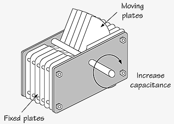
Could a variable capacitor be designed?
The most thought of design for one was to simply have a screw-like device that can be used to adjust the distance between the two plates, increasing or decreasing the capacitance.

A common design when the term "variable capacitor" is searched online is the one below. The fixed plates are separated by some common distance. A "knob" may be turned which will move extra plates into the region between the fixed plates, this in turn does two things. It first reduces the spacing between plates as well as increasing the area, both of which will in turn increase the capacitance, the amount of charge that may be stored.
There is a long list of capacitor types that range from precision and material to cost and durability.
We have learned today that voltage across capacitors must be continuous... not constant. It cannot change abruptly, this resistance to change in voltage is a characteristic of all capacitors. A discontinuous change would require an infinite current which is physically impossible. Current on the other hand may change suddenly. Under DC conditions if we were to change a capacitor in serries with a very large one, nothing would change, but when we arrive to AC conditions things we are told will get interesting.
Energy in a capacitor may be derived by integrating power. Power may be expressed as the product of voltage and current, while current through a capacitor may be expressed as the product of its capacitance and the change in voltage over time. By integrating power with respect to time a formula for energy may be expressed as below.

How can the graph, below, of current as a function of time be expressed as voltage over time?

Below is our representation of the voltage as a function of time based on the graph from above.

Next, given a simple RC circuit, let us use the knowledge from above to calculate the energy of the capacitor.

In this case the voltage across each capacitor is equal to the resistor that is in parallel with it and by simply plugging in those values energy may be calculated.

Below, given voltage versus time we took the derivative to find current versus time. The cosine graph on the left becomes a sine graph, or in the words of Javi, "it is just a phase shift".

Professor: "We are going to do something amazing, something you've wanted to do since the beginnig..."
Student: "...drop?"
Setting up a simple RC circuit for lab. Below is the schematic of the circuit we will build.

Below is the circuit we built using a 100 Ohm resistor and 1 micro Farad capacitor. We will be sending a sinusoidal and triangular signal into the circuit.

Below is the prediction for the lab. Applying a sine input will result in a phase shift current response by the capacitor. While applying a triangular input voltage will trigger a square response by the capacitor.

Below we first used a sinusoidal input voltage set to 1kHz, 2V, and zero offset. Similarly to what we saw earlier, we should see a sine-like graph for the applied voltage and a phase shift graph that is cosine-like representing the current.

Yellow is the input voltage and blue is the current.

Below we see again the same as the above oscilloscope graphs except with some adjustments. The input voltage is now at 2V, frequency to 2kHz, and still zero offset.


Also discussed earlier, a triangular voltage would result in a triangular current. Below we generated a square input voltage of 4V , at 100Hz, and zero offset.


How do capacitors react in series or in parallel?
Capacitors add up oppositely to resistors, when in series you must first add their inverses while in parallel they may be added directly.

INDUCTORS
Quickly we touch bases on inductors now. They are just a coil of wire and their symbol in a circuit diagram looks just like that. Oppositely to capacitors, inductors resist sudden change in current and do not hold energy for any significant amount of time.


Here we have written the expression for an inductor. It is proportional to the product of the number of coils squared, area, and permeability of free space constant, and inversely proportional to the the length.


No comments:
Post a Comment